|
We have summarized practical points when designing compression coil springs and determining drawing specifications.
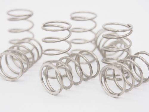
Compression coil spring design 5 points
Point 1 Shape of push spring end
Typical end shapes of Compression coil springs are as follows.
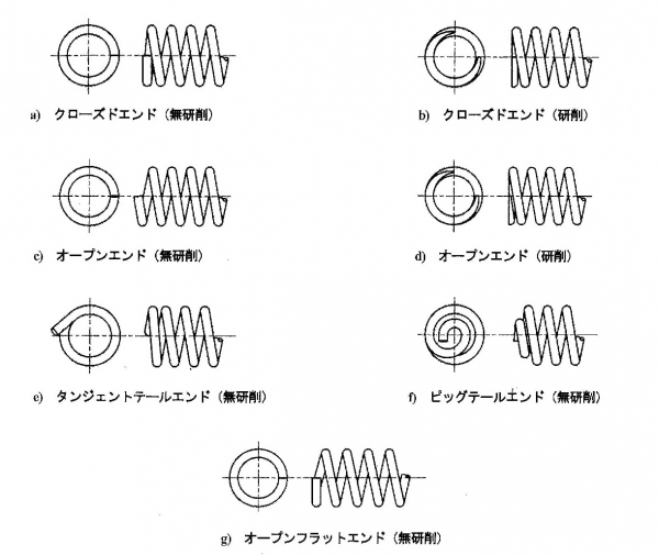
Generally, "b) closed-end grinding" is used, in which the end face of the spring is ground flat to stabilize the spring end mounting. The end face is ground about 3/4 turn.
When the wire diameter is 1 mm or less or the spring index (spring index = coil average diameter ÷ wire diameter) is large, the end mounting is stable without grinding the end, so "a) Closed end no grinding" I often do it.
Grinding has more processes, so the cost is naturally higher. You may also need a special jig for shaving.
The shape of the end of the push spring is determined by considering the balance between stability and cost when the spring is attached.
Point 2 Precautions when specifying the tolerance of spring characteristics
The spring characteristics are (1) the load at the specified length and (2) the spring constant.
When deciding the specifications in the drawing, basically, the tolerance of "spring characteristics" is not specified.
If it is absolutely necessary to specify the "tolerance", specify the tolerance (tolerance) of "(1) Load at the specified length" of "Spring characteristics".
Furthermore, if it is deemed necessary, specify the tolerance of "②Spring constant".
If you specify a tolerance for spring characteristics, the free length is a reference value. There is no tolerance for free length.
If both "spring characteristics" and "free length" are tolerated, mass production may become difficult and costly.
Also, the specified load and spring constant cannot be specified anywhere the spring bends. There are the following rules.
"Rules for load when specified length"
Specify the specified length so that it is between 20 and 80% of the total deflection.
The load must be 80% or less of the maximum test force.
"Rules for spring constant"
It is calculated by "difference in load" ÷ "difference in deflection" at two load points at 30 to 70% of the total deflection.
The load must be 80% or less of the maximum test force.
* Basic calculation formula
Total deflection = calculated free length-calculated close contact length
Calculated close contact length = (total number of turns-1) x wire diameter + sum of thickness at both coil ends
Please refer to the following for the maximum test force of the spring.
Point 3 Spring index
The spring index is the average coil diameter divided by the wire diameter.
When written with a symbol, c = D / d. The spring index is also called D-by-D.
It is recommended to design the spring index in the range of 3-22.
Also, the tolerance range changes depending on the spring index.
If the spring index is too small or too large, workability becomes a problem, making it impossible to manufacture, increasing variation, and increasing costs.
Point 4 Aspect ratio
The aspect ratio is "free length" ÷ "coil average diameter".
The average coil diameter is ("coil inner diameter" + "coil outer diameter") / 2.
The aspect ratio should be 4 or less. If it exceeds 4, the push spring will buckle and the load will not be as calculated.
If you absolutely must design with an aspect ratio of 4 or more, we will provide "guidance" in consideration of buckling.
For guidance, a guide rod is placed inside the spring, or a spring is placed inside the cylinder to support buckling.
When guiding, it is necessary to consider the relationship of friction with the guiding that comes into contact, and the fact that the load does not come out as calculated when contacting.
It is more essential to perform actual mounting experiments as well as calculations to test loads and life.
In addition, it is said that an aspect ratio of 0.8 or more is desirable. This is because it is necessary to secure the minimum number of effective turns.
If the aspect ratio is small, the number of effective turns will be small, and the actual spring characteristics will vary widely, so it is often the case that the spring does not meet the design calculation.
Point 5 Other precautions
① Effective number of turns
The number of effective turns is preferably 3 or more. If the number of effective turns is small, the variation in spring characteristics will increase.
② Total number of turns
If the spring characteristics are not specified, the total number of turns tolerance is ± 1/4.
If the spring characteristics are specified, the total number of turns is a reference value.
③ Designation of close contact length
The close contact length is generally not specified.
When specifying, "total number of turns" x "maximum value of wire diameter".
Please note that it is different from the calculation formula for the close contact length (see point 2 basic calculation formula) .
④ Pitch
The pitch should be 0.5D (0.5 x coil average diameter) or less.
If it exceeds 0.5D, the average coil diameter will change as the load increases, and it will not match the value calculated by the spring design.
The calculation formula for spring design is based on the assumption that the pitch is extremely small. If the pitch is large, it will need to be corrected.
In general, the formula for calculating the pitch is as follows.
Pitch = (free length-contact length) ÷ effective number of turns + wire diameter
If you have any questions about spring design, please feel free to contact us.
|

![]()


